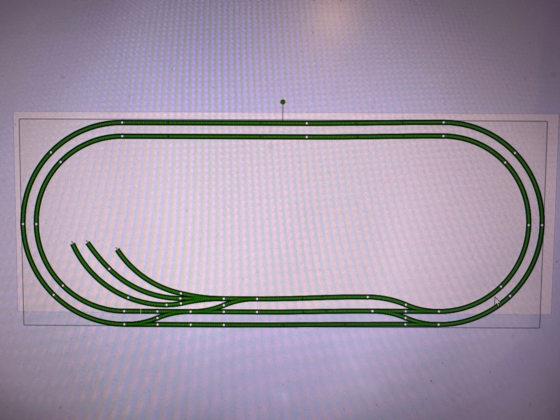
The model railway module will have a slot for a 100 × 20 cm (40" × 8") panel for the control electronics, the purple rectangle in the track plan above. Connection to the layout will be made using multiple D-Sub connectors. This make it possible to demonstrate and test Traintastic using different electronic solutions for model railroad control.
DCC/S88 logic board
A commonly used setup, DCC accessory decoders for controlling turnouts and signals, and S88 for feedback sensors.
Technically the most different solution, DINAMO is a track driver system, each block has its own booster. This makes it possible to run Analog and DCC trains at the same time.
1x RM-C/2 - PC interface
3x TM44 - Track driver, 4 fold, 16 current detectors (4 per driver)
On the wish list, BiDiB is not yet supported by Traintastic due to leak of testing hardware.
It will take some time to build it and gather all the required hardware, some I have already, other hardware is sponsored and I will need to buy additional stuff.
Not yet, a future version of Traintastic will include this layout for different system types including simulation support, but that will take some time to develop.
DCC-EX would be another option indeed, I’ve already a DCC-EX system with ethernet to, that I use for testing, the DCC/S88 will be the first to build as it is most generic.
For the VPEB system there are a few dealers in Europe, but none in Australia as far as I know. The DINAMO system has one disadvantage, it can not operate without a PC, the PC must keep track of all trains and link/unlink the blocks so there are no shorts. They (VPEB) don’t have their own control software so the need others too support it. Last december I got a call from the main representative if I would support it in Traintastic as well, I said yes, so the donated some hardware DINAMO support will be added in v0.4.0 as well, still working on it.
Hope you get the chance to test also the Yamorc railcom-feedback modul YD6016LN-RC.
It will be connected with the yamorc YD7010 via loconet, but can be connectet via USB directly with the Laptop as second interface, means, this feedback-modul can be used beside (“with”) every other DCC-zentrale, for example also the z21, but also completely independent (even Märklins CS2/CS3 or others) if the RC-Cut in the DCC-Signal on the track is implemented. At least there must be a booster which is able to cut the RC-Cut and you can read by traintastic every RC-Messages from the Dcoder, sendet on the track.
Yes that would be nice, although I expect it to work with Traintastic, I’ve a DigiKeijs DR5088RC (16+1 input LocoNet RailCom detector), the DR5088RC was also designed by Karst Drenth, so the YD6016LN-RC most likely is an improved version of the DR5008RC.
That won’t work, the limit here is LocoNet, for standard RailCom the LocoNet OPC_MULTI_SENSE message is used, it can only carry an loco address and a detector address. The DR5088RC and YD6016LN-RC have an option to use the highest bit of the loco address or detector address as direction indication. Traintastic supports both. Alternative is the unofficial OPC_MULTI_SENSE_LONG message (also supported by Traintastic) that can be enabled on the DR5088RC and YD6016LN-RC, this message can carry more RailCom data, e.g. quality of service and some other.
For the ECoS these can’t be used, the ECoS LocoNet modules doesn’t forward OPC_MULTI_SENSE to the ECoS, only normal detectors OPC_INPUT_REP work, I’ve tested that about two year ago. (Might be added, but I think ESU prefers to sell their own RailCom detectors.)
For the DCC/S88 board, the first one I’m going to build a YaMoRC YD8116, it is a really nice DCC decoder that supports DCCext (RCN-213) aspect commands. It has 16 outputs you can freely map to all kind of signal types.
For CBUS/VLCB I don’t now yet, that’s for the future (Suggestions are welcome, will need 10x3=30 sink outputs.)
Looks interesting from a port density/board and price per board….
Cbus/vlcb boards I don’t think are interesting to me to drive signals.
AFAIK I haven’t seen options to blink a led in set and forget. Programming a signal head with that would be a pain
Some merg non Cbus ( based on detection might be useful )
There is a CANPAN board that has 32 inputs and 32 outputs. The inputs and outputs are organised in a 4x8 matrix to save pins. So here you can use one board for your 30 LEDs.
The matrix has 4 anodes and 8 cathodes that are activated in turn by the board. Put an LED in the connection point between an anode and a cathods.
The LED outputs work with constant current so there is no need for resistors for each LED.
The CANPAN is actually designed for control panels. (hence its name) But it is common to use it for signals.
There is a newer version (CANPAN3) in the pipeline that has a feature where the intensity of each LED can be controlled individually. This is useful if the LEDs require different amount of current for similar intensity. This is the case when you have different colurs.
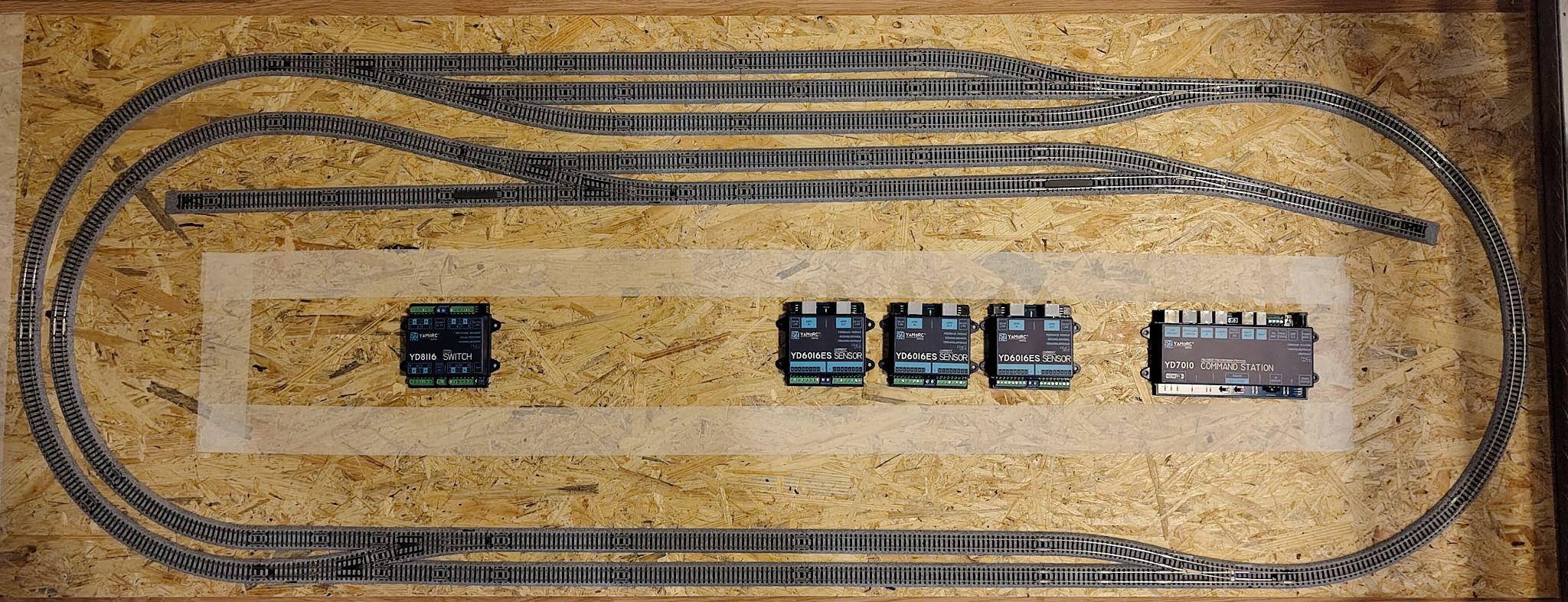
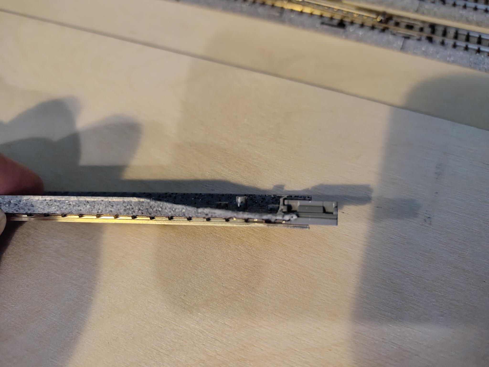
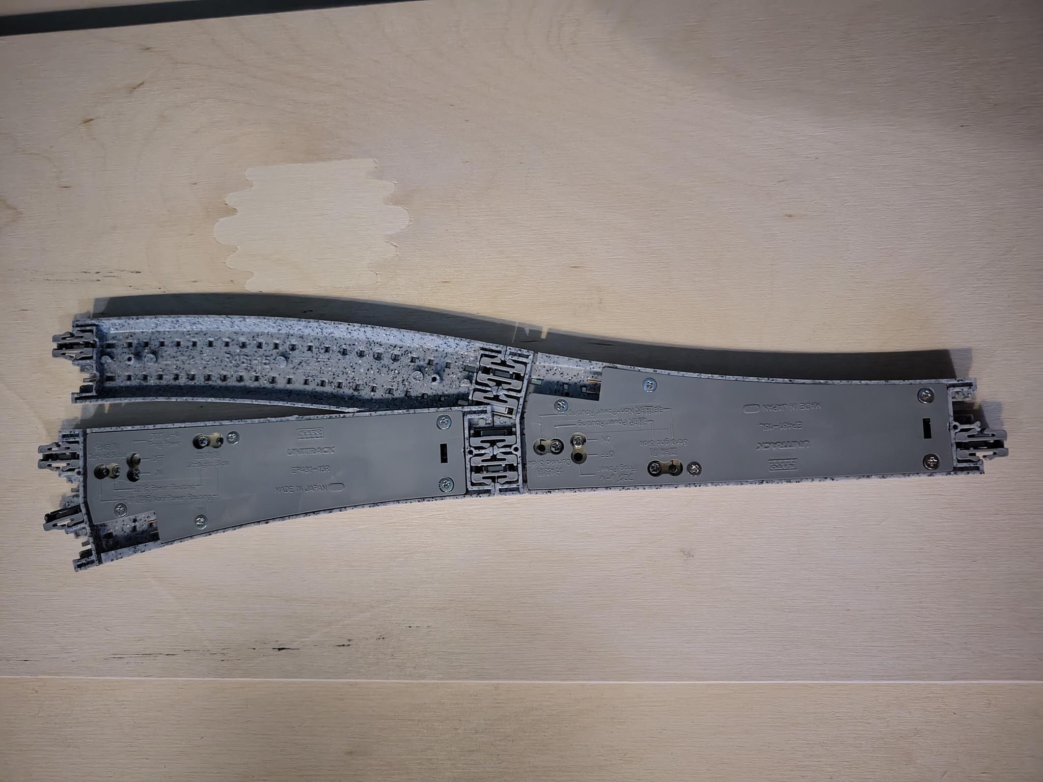
Earlier this week all the Kato tracks arrived, this evening I’ve made the trackplan to see if it matches the design. There is one thing i need to fix, the Kato track systems has special rail pieces for connecting to the turnouts as the beds will collide, top left I’ve a turnout with a turnout and a curve connected, that doesn’t fit. I’ll cutoff something of the curve to make it fit (I’ve a few spare in case I mess up)
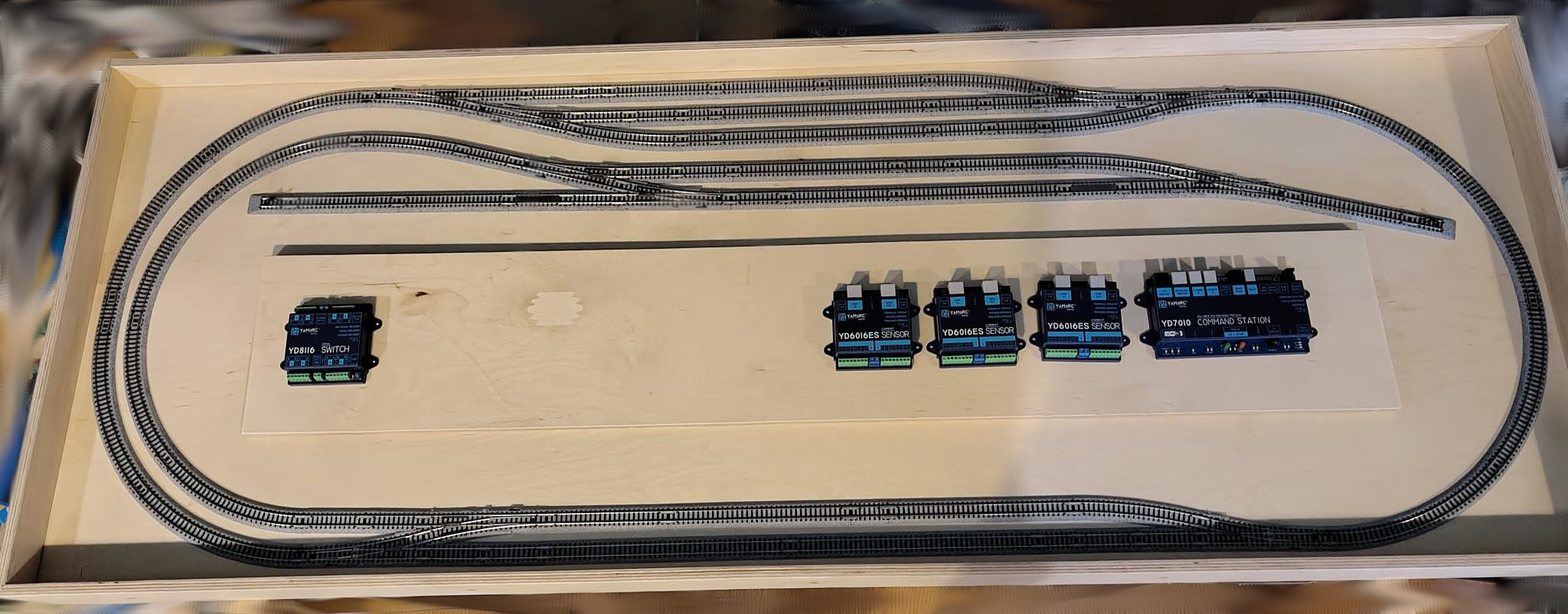
The taped section (120x20cm) is for the logic panel, I’ve placed the YaMoRC devices as example. Still need one additional YD8116 and two YD8008 to complete the DCC/S88 logic panel.
Next is building the wooden frame, or actually, letting build it, a local club member (retired carpenter) will build it for me
@MZwa
For the CBUS panel I want it to be 100% CBUS/VLCB, not mixing it with other stuff.
ArCoMoRa could be an option for a DCC-EX DIY panel.
Ideally there would be a panel for each system supported by Traintastic, that would really help with testing and finding issues…but that will be very expensive, so that will be a dream or sponsoring…
@sven-e
The CANPAN is really interesting, for the signals on this layout it is not ideal, the signals are common anode and the LEDs have an resistor, I kind of need that for other hardware. Then the easiest is most likely using two nodes with 16 outputs each.
Would be cool to use a CANPAN for a control panel to demonstrate the power of the CBUS system.
Is there a kit available for driving solenoids? The Kato turnouts have only two wires, you have to reverse the polarity to switch them, but I’ve small convertor PCB’s so they can be controlled by two normal outputs.
Yes, there is a CANSOL kit. It can control 4 solenoids. This is intended for the PECO solenoids that require a lot of power.
If I understand the Kato turnouts has solenoids that don’t require much power. I think they also have switches that break the power when the turnout has moved to its new destination. If that is correct then you could operate the Kato turnout with a two pole switch that changes polarity of the two wires of the turnout. This treats the Kato solenoid motor as a slow motion Tortoise or Fulgurex. If that works then you can use a CANV4BIP board which is designed for Tortoise/Fulgurex. It can control 4 turnout motors but also has 8 input pins that you can use for the track sensors.
I had one issue where a turnout and a curve needed to be connected to a turnout, that doesn’t fit with the Kato system by design, so I modified the curve a bit and now it fits
I took some time to re-evaluate the track plan, I came to the conclusion that it had some limitations:
There can’t be a train waiting in the station (bottom two tracks) if one departed from the branch line station.
Once a train from the staging area (top three tracks) dropped off wagons at the siding and another or the same loco picked them up again the sequence can’t be executed again because the loco is on the wrong side of the train.
Besides that Domburg Train Support donated two TM44’s and an OC32/NG and a DTRv2/PAR relay module. The relay module is interesting, normally when using DINAMO each block needs its own track driver. A TM44 contains four track drivers, so with three TM44’s I can drive 12 blocks. So the staging area needs three track drivers, one can imagine with a big staging area this will become expensive. The solution: use a single track driver and a relay per staging block, now a single track driver can control the whole staging area Downside off course is that only one train can enter/exit the staging area simultaneously. (Currently iTrain adn RocRail support this, RocRail and Koploper does not support this relay trick.)
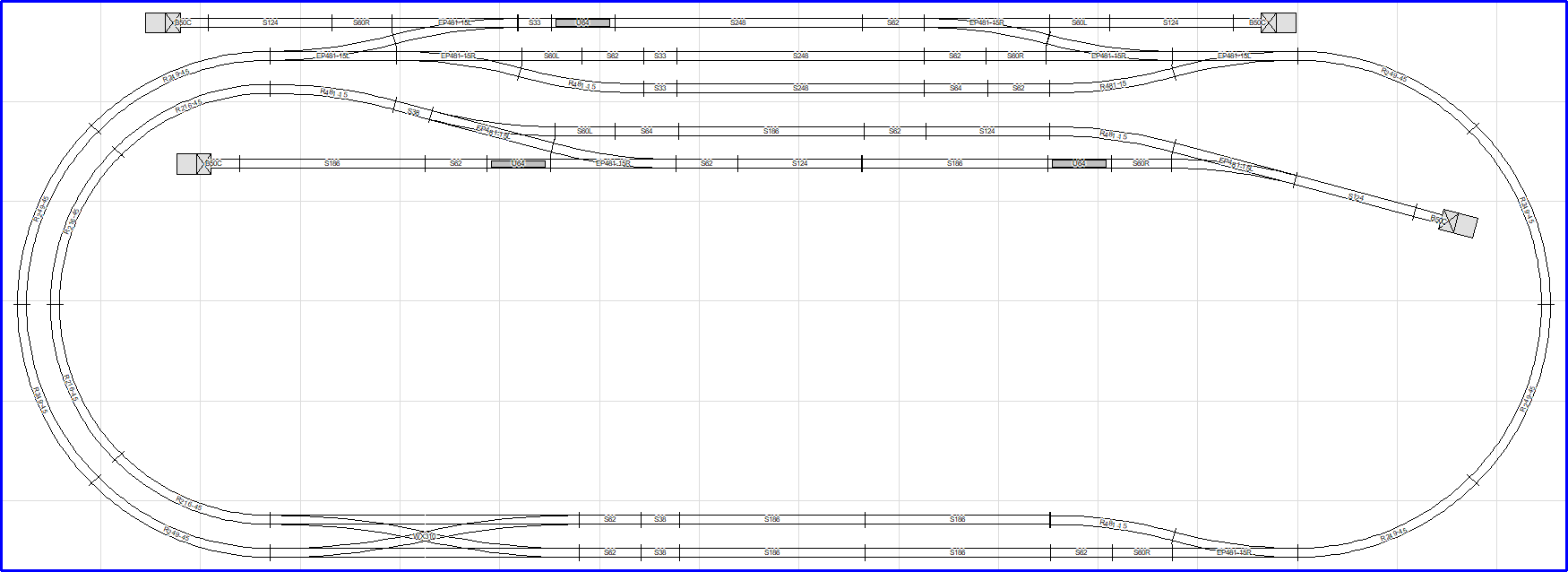
That all got me thinking…my goal is a small layout that can demonstrate as much as possible. So I modified the trackplan a bit:
Replaced the crossover by a double crossover, now trains between the station and branch station can pass each other at the station.
Added two extra branches to the staging area, to make is possible to decouple the goods train loco and couple another loco to the wagons so the sequence to the siding can be executed again.
These changes will require 14 track drives, but by using the DTRv2/PAR relay module we can reduce this to 12
The Kato double crossover is electrically a single turnout, all turnouts are either straight or diverged. To support that I’ve developed the turnout linking feature
These changes also will require some additional relays for the DINAMO panel to connect some turnouts to the correct track driver based on their position.
I’d hope this will be my final track plan, the good thing is there are even more features now that can be demonstrated

 Huge thanks to Drenth Design & Consulting B.V. for donating the command station and the three feedback modules.

 DINAMO support will be added in v0.4.0 as well, still working on it.