MERG CBUS/VLCB hardware support

Hi All,

I’m looking into support MERG CBUS/VLCB in Traintastic. I spend some time reading the protocol documentation and made a start with building the basic pluming in Traintastic to support CBUS/VLCB.

Real CBUS/VLCB testing is a bit an issue as I don’t have any CBUS/VLCB hardware available yet, so if you have CBUS/VLCB hardware and wanna help, please let me know!

Hi Reinder,

I’ve forked the repository and pushed my files, also did a pull request.

As I see, you have also prepared files for engine message. I have no central station for CBUS. There are the MERG CANCMDB and the CAB Control as Kits for members of MERG. My focus is currently on control and feedback devices. I plan to build some own devices with more ports, i.e. with the PIC18F47Q83 - 128kByte Flash, 13kBytes RAM, 1k EEPROM, 40 Pins DIL Package and up to 36 I/O pins. MERG uses only the smaller 28Pin controller within their kits.

I am considering whether to order the CANCMDB control unit and the CANCAB2 hand controller. The CANCMDB has only a small H-Bridge for max. 1A, that’s not much. I am thinking about a central with the PIC18F47Q83 and my own booster, which has a H-Bridge without integrated bridge controller would be good for 5-10A with the MOSFET’s.

But I think, for testing purposing, it would be nice to have the original kits, too.

I have the complete equipment, Scopes, Logic Analyzer, PIC progammer and so on for Hardware testing, so I can take this part.

Greetings,

Tom

Hi Tom,

Saw the PR, after a quick scan it seems to be a copy of Traintastic DIY with a few minor changes, I’ve pushed my skeleton for CBUS/VLCB support, I think is it is best we work from that (don’t want to be rude ;)).

It has:

  • IOHandlers for CANUSB and CANEther
  • Track on/off logic
  • EStop logic
  • Rx/Tx logging option
  • At startup it send a RSTAT and QNN message.

Nothing is tested yet, so free to give it a try and report or fix the issues :slight_smile:
The CANUSB serial settings are now fixed at 115k2 8N1, just a guess.
For CANEther, there is probably a default port number, for now it is 0.

What is missing:

  • Locomotive control via DecoderController
  • Input monitoring via InputController
  • Output control via OutputController
  • Simulation support

I’m also considering to become a MERG member and order some hardware, based on some prices I’ve seen (modules are not that expansive), its still about 150-175 EUR for Membership+CANVOUT+CANCMDB+CANCAB2E+CANUSB+shipping+import+vat :frowning:

It would be great if you can do testing (and fixes :)), using the logging feature it is possible to log all traffic, I can use that to build a simulator which makes it easier to debug/test without hardware. Traintastic has protocol level simulator for all most all supported protocols :slight_smile:

We can start with the input/output, the things you need first, then do the CANCMDB later on.

A question:
Traintastic normally uses channel + address for identifying inputs/outputs.
How does input/output identifying work on CBUS/VLCB? Is is node/module based?

Best regards,
Reinder

Moin Reinder,

I worked as IT-Security and IT-Infrastructure Admin, not as programmer and I’m really not a C++ programmer, especially not with modern software design. I have many years of experience with C in hardware-related environments, i.e. microcontrollers, 8051, 68HC11, ATMega, a little bit STM32 and system-related programming under various operating systems in C. Also in Electronics, analog and digital. PIC controllers are new to me, Harvard architecture instead of von Neumann, which is quite a change :wink:

When I asked you if you would support CBUS/VLCB, I didn’t expect you to write code; I thought I would have to do it myself. So it’s really nice, that you build the skeleton for CBUS/VLCB, thank you very much!

CBUS/VLCB uses the producer/consumer model. So you don’t need to address a node, you have to teach the node on which event from which node it has something to do. But CBUS has also the possibilty to do direct addressing. There are two address configuration modes, SLiM with DIP Switches and FLiM. I think SLiM can be ignored; new nodes all use FLiM.

Normally you have <OpCode><Nodenumber Hi><Nodenumber Lo> followed by the Eventnumber, where the nodenumber is the producer node. A consumer could react on this event. MERG has a tool to setup the nodes and to teach them, what to do. FCU is the older one (only for Windows) and MMC is the node.js based tool for all platforms. Also JMRI has integrated these functions. I don’t know (and understand) how complete Rocrail has these functions.

With direct addressing <OPCode><NN Hi><NN Lo><Devicenumber Hi><Devicenumber Lo> the nodenumber will be ignored, there are OpCodes for this, i.e ASON (98). The different is, that every input and every output from a I/O node has an own device number.

The system is very flexible, I haven’t read all the docs until yet. I think the primary document is the Developer’s Guide for CBUS. I consider this to be basic documentation, also for VLCB.

However, I read the documentation more from a microcontroller perspective :wink:

Greetings

Tom

PS: This editor kills text within <> if it is not formated as Code.

Moin Tom,

Happy to assist, I like the puzzle of a new protocol and fitting it into Traintastic’s HAL, with each protocol the HAL is challenged as each protocol has its own specialties which somehow must be made general so the rest of the software doesn’t have to know about the hardware. So feel free to ask question if you need help on the CBUS/VLCB implementation, or just provide feedback and I do most of the implementation, that is also fine :slight_smile:

I’ll read the Developer’s Guide for CBUS with the PC perspective then :wink:
Need to build a mental model of the system, once it clicks in my head I’ll know how to implement it into Traintastic.

The CBUS/VLCB interface has a send() function (since Saturday), it can be used to send messages directly to CBUS/VLCB for testing/experimenting.

Example using a push button on a board:

local cbus = world.get_object('cbus_1')

world.get_object('push_button_1').on_pressed(function ()
  cbus.send([0x0A]) -- Request ESTOP
end)

The send() argument is a table with the data bytes in the CAN message.

Greetings,
Reinder

Did some reading on the short/long events.

For the OutputController two Channels are needed:

  • Short event
  • Long event

Address is the event number/device number. (the label should change then for clarity)

The nodeId for Traintastic sending is 0xFFFC (CANUSB).

The you’ll get something like this (edited the screenshot a bit):

As there is support for sending raw DCC commands, two additional channels can be added as well:

  • DCC Accessory
  • DCCext (RCN-213)

@DL7BJ would this work for you / CBUS?

Moin Reinder,

I’ve tested ACON, ASON and ASOF. I have configured the CANVOUT node with MMC and three events.

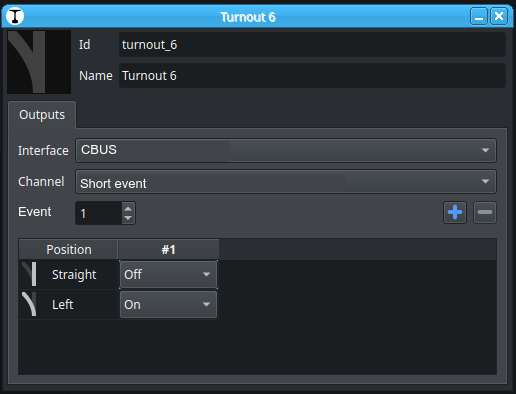
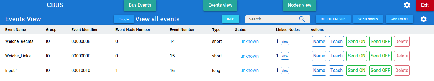
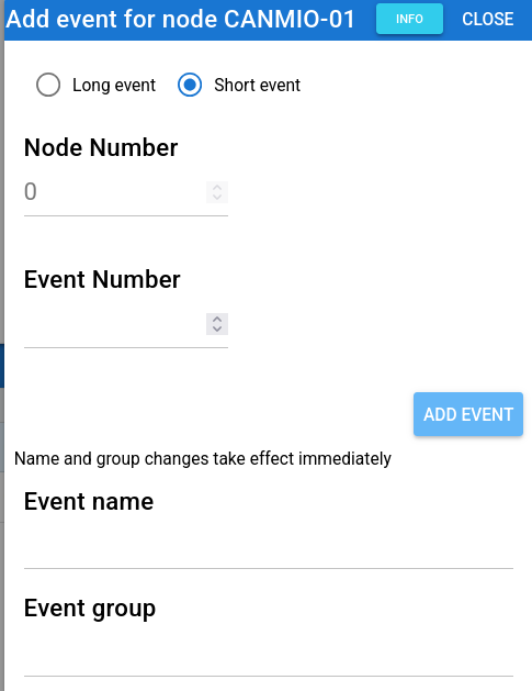
There are the events 14 and 15 as short events and the event 16 as a long event. Short events don’t use a node number, every node with configured short events reacts on this event. Long events need the node number.

This test was made with DecoderPro (JMRI)

JMRI  > >  CBUS |  ASON EN:15   Short Event On ON event using the event, no node. [+15] Dyn Prio: 2 Min Prio: 3 CAN ID : 126 [5fe] 98 00 00 00 0F RTR:N  

JMRI  > >  CBUS |  ASON EN:14   Short Event On ON event using the event, no node. [+14] Dyn Prio: 2 Min Prio: 3 CAN ID : 126 [5fe] 98 00 00 00 0E RTR:N  

JMRI  > >  CBUS |  ASOF EN:14   Short Event Off OFF event using the event, no node. [-14] Dyn Prio: 2 Min Prio: 3 CAN ID : 126 [5fe] 99 00 00 00 0E RTR:N  

JMRI  > >  CBUS |  ASOF EN:15   Short Event Off OFF event using the event, no node. [-15] Dyn Prio: 2 Min Prio: 3 CAN ID : 126 [5fe] 99 00 00 00 0F RTR:N  

This switches Out 7 and Out 8 ON and then Out 7 and Out 8 off, without a node number, only the event is needed. The CAN ID 126 is the ID of DecoderPro.

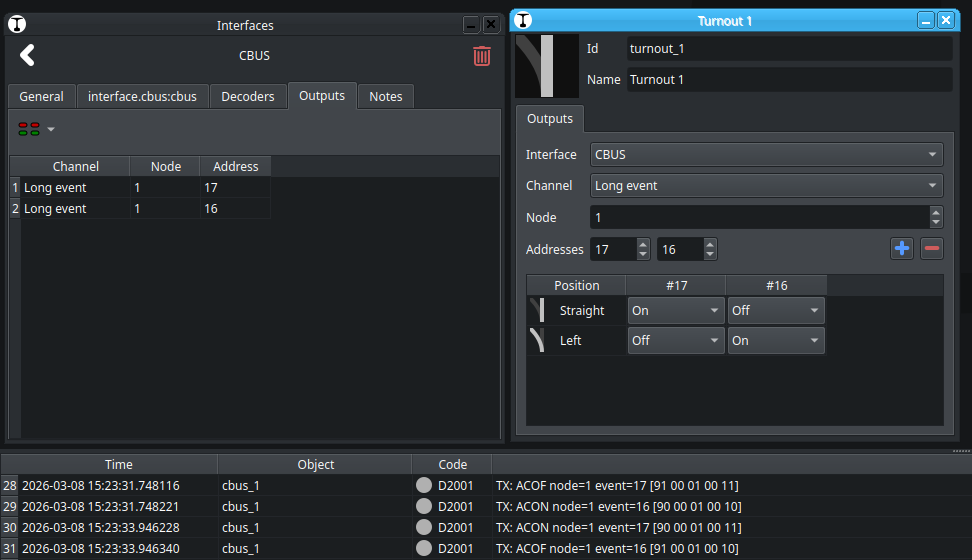
With the long event I have to add the node number of the node, which should do the event, as you see the node number is 1:

JMRI > > CBUS | ACON NN:1 EN:16 Long Event On ON event using the node and event. [+n1e16] Dyn Prio: 2 Min Prio: 3 CAN ID : 126 [5fe] 90 00 01 00 10 RTR:N

Both options are well running with DecoderPro.

Then I add a point to Traintastic.

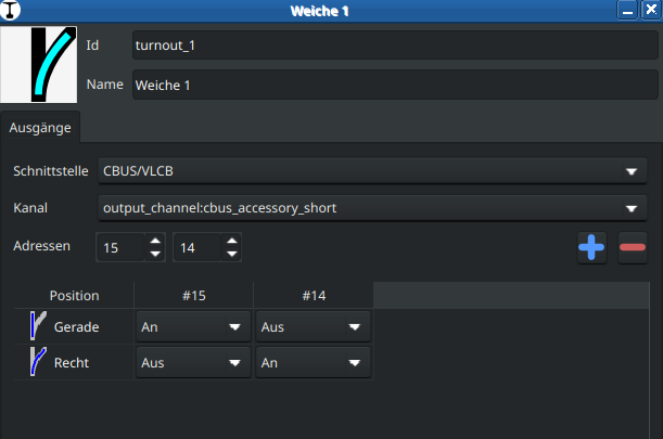
This runs also very well and toggles Out 7 and Out 8 with the short events 14 and 15.

026-03-06 22:46:31.487358 cbus_1 D2001: TX: ASOF node=65532 device=15 [99FFFC000F]
2026-03-06 22:46:31.487391 cbus_1 D2001: TX: ASON node=65532 device=14 [98FFFC000E]
2026-03-06 22:46:34.625796 cbus_1 D2001: TX: ASON node=65532 device=15 [98FFFC000F]
2026-03-06 22:46:34.625830 cbus_1 D2001: TX: ASOF node=65532 device=14 [99FFFC000E]

But a problem exists with the long event:

2026-03-06 22:48:03.996735 cbus_1 D2001: TX: ACOF node=65532 event=16 [91FFFC0010]
2026-03-06 22:48:05.549055 cbus_1 D2001: TX: ACON node=65532 event=16 [90FFFC0010]
2026-03-06 22:48:07.191648 cbus_1 D2001: TX: ACOF node=65532 event=16 [91FFFC0010]

Traintastic sends its own node number here, not the number to which the event should be sent.

The definition of short event and long event here by MMC is slightly different from that in the developer’s guide. Short events are based on the P/C model, long events on hardware addressing.

If you switch to short event, the node number is always 0. So traintastic should use with long events the node number as address to which the event should be sent, not the own number.

I am still wondering whether the configuration of the nodes should be implemented in Traintastic or whether it would be better to use MMC for this. This could be quite complex, because various nodes can have completely different settings, including the teach mode. At the moment I think the configuration of the nodes with MMC is ok.

But, it’s very nice that the basics running fine!

Greetings,

Tom

Moin Tom,

Many thanks for testing it!, did you need to make any changes to the CANUSB iohandler, or did it just work?

Are Short event / Long event the common terms to use? If so, I’ll name them like that in Traintastic too.

For Long events adding a single Node number property between Channel and Address would work I think. The only limitation then is that e.g. a signal can only send Long events to a single node, mixing is not possible (but that would be weird anyway.)

Have you tried the Lua send() function?

When the CBUS/VLCB interface goes online it also sends a QNN, does the CANVOUT module respond to that? It would be nice to have a list of nodes/modules in the interface dialog. (That info can also be used for the node option for long events.)

I agree with you, using MMC for configuration is best. Traintastic should focus on control and automation.

Greetings,
Reinder

p.s. I just commited basic support for CANCMDB :slight_smile:

Moin Reinder,

I didn’t need to change anything, it runs out of the box.

In the developers guide a short event is an event without data bytes and a long event an event with 1 to 4 data bytes. I will ask at the MERG forum for the right terminology for long and short events and the meaning in MMC. I see differences between MMC and documentation, but I may be mistaken.

I have not testing Lua until yet. I will look for QNN. At the moment I have only the CANVOUT und my own hack of a node to learn the basics. CBUS/VLCB is a new one for me and Traintastic also, you know :wink:

I will see what I could test in the next days. It’s fine that the basic communication runs.

The CANCMDB and the CAB control should arrive at Monday.

Greetings

Tom

Moin,

just reading a little bit about short and long events.

We always have to look at it from the node’s perspective. All events of a node can be taught. If the event is a short event, the node number is ignored. If the event is a long event, the node will react to it if it has been previously configured to <node number>:<event number>.

So, if Traintastic sends an event with <65532:256> only nodes that have learned this event will respond to it.

I test it with JMRI’s DecoderPro, there I could change the sending node number. That is flexible, but could also be an problem. If I have some hardware switches on inputs of a node, i.e. to switch a point a message is generated with <node number:event number> If the generated event is a short event the receiving nodes ignore the node number. If the event is a long event receiving nodes must be configured to react on <node number:event number>

That’s very flexible.

If Traintastic should switch a point and a hardware switch too, than both must use the same sending node number, if it is a long event.

So I think we need here the possibility to configure the sending node number which Traintastic uses and the event number for this bus message:

Then the “virtual” switch has the same function as the hardware switch connected to node.

That would be the most flexible configuration for short and long events and the user could choose to use a short event or long event without teaching every node for the events send from Traintastic with the node number 65532.

The input handler should read every bus message and have a look if an event is configured for a sensor regardless of type to show the state. A sensor could be a reed contact, feedback for point position, occupied sensor and so on. All these input sensors states should be visualized if they are configured in Traintastic. So the input handler needs also a configurable node number and eventnumber for short and long events.

These are my thoughts and idea :wink:

Greetings

Tom

Moin Reinder,

Yes, it will do! :slight_smile:
2026-03-07 15:40:35.191159 server N1007: Listening at 127.0.0.1:5740
2026-03-07 15:40:35.191192 cbus_1 D2001: TX: RSTAT [0C]
2026-03-07 15:40:35.191202 cbus_1 D2001: TX: QNN [0D]
2026-03-07 15:40:35.387386 cbus_1 D2002: RX: PNN [B60001A5340D]

Greetings, Tom

The CANCMDB and the CAB control should arrive at Monday.

Looking forward to that :slight_smile:

Thanks for the investigation, explanation and ideas, it really helps!

I’ll rename it to: Short event / Long event
Long event will get an extra node property, default can be 65532, but user can change it.
Another idea: change the address(es) label to event(s), that will fit in better with CBUS naming.

Might take a few days depending on how much time I have, need to modify the HAL to add node awareness.

After that I’ll have a go with the input logic. Does the CANVOUT module have inputs? (Based on the name I guess not…but just to be sure.)

026-03-07 15:40:35.387386 cbus_1 D2002: RX: PNN [B60001A5340D]

This is interesting, we can use this to build a node list, that list can also be used as predefined values for the input/output node property.

Greetings,
Reinder

Moin Reinder,

the CANVOUT is a multipurpose board, it could be used for many things. Standard are 8 inputs and 8 outputs. But it could also used for Servos. I use the universal firmware CANMIO.

2026-03-07 19:46:13.966667 cbus_1 D2002: RX: ACON node=1 event=14 [900001000E]
2026-03-07 19:46:14.155048 cbus_1 D2002: RX: ACOF node=1 event=14 [910001000E]
2026-03-07 19:46:18.342137 cbus_1 D2002: RX: ACON node=1 event=13 [900001000D]
2026-03-07 19:46:18.495763 cbus_1 D2002: RX: ACOF node=1 event=13 [910001000D]


I think the simplest way for a node list are the node description files of MMC in JSON format.

These files includes the full description of any currently and in the future existing node and uses the naming convention.

I will do some tests with Lua now.

Greetings

Tom

Moin Tom,

I’ve rewritten part of the OutputController addressing logic, it was a big change but it is now future prove to support more addressing schemas in the future :slight_smile:

The channels are now named Long event and Short event and Long event now has a Node property:

How does it work for the inputs, do you have to configure/learn what short/long event to sent when an input changes?

The node description files are interesting, it would be nice to use them.

Greetings,
Reinder

Moin Reinder,

the 8 inputs of the CANVOUT node have fixed long events. I flashed the board with the Universal MIO firmware from Ian, but it was to late yesterday to do some tests. This firmware has many more possibilities.

Normally, as I understand the docs, short/long events are configured at the receiver, not the sender. The node number is ignored for short events.

I will made some test and report back.

Greetings

Tom

Moin Tom,

Looking forward to the test results, once they are in I’ll make a start with the InputController logic. Then the basics are in place, although I expect that we need to some some fixes :slight_smile:

For CANCMD the keep-alive is missing, that needs to be added too.

Greetings,
Reinder

Moin Reinder,

short info:

I tried the Universal-VLCB firmware, have had a problem with the inputs, but solved that. But there a some issues to compile the latest Github version, I am in contact with Ian about that.

With the Universal-VLCB firmware we could setup own events for the inputs, the original CANVOUT software uses only predefined events. This will be more flexible for further tests.

The CANCMDB and CANCAB are arrived, but I haven’t time to solder the kits, until yet.

Greetings

Tom

Moin Reinder,

the main problem to compile the Universal-VLCB was the PIC controller. I replace the original PIC18F26K80 with a PIC18F27Q83, because this code needs some functions like PWM with the PWM module of the controller, which the PIC18F26K80 don’t have. The controller are pin compatibel.

Now I can configure the produced events with MMC, this is a input event with the eventnumber 1234

ON

mergAdminNode: EventSend : {“eventIdentifier”:“000104D2”,“nodeNumber”:1,“eventNumber”:1234,“status”:“on”,“type”:“long”,“count”:1}

OFF

mergAdminNode: EventSend : {“eventIdentifier”:“000104D2”,“nodeNumber”:1,“eventNumber”:1234,“status”:“off”,“type”:“long”,“count”:2}

But that’s not all with the Universal-VLCB. I could configure some actions, this is a little bit like scripting.

With produced event I set which channel triggers the event. All consumend event can be configured for some action. Here I toggle the LED on channel 1 (output) if channel 9 (input changed) triggers the event. There are the possibilty to wait for a time, to flash the output and so on. With these functions only this node with 8 inputs and 8 outputs could used as occupance detector and controls a level crossing with barriers or for many other things.

I like it :wink:
Greetings, Tom

Moin Tom,

Nice find, a minor difference in the PIC controller type. This system is indeed very flexible, you can program stuff once and then operate without a PC.

This is also very useful for building control panels, once interlocking becomes a thing it is not sufficient I think, but then sending the event from the control panel to Traintastic (the PC) which can in turn send event(s) if the path can be set or flash an error led on the control panel. Maybe I should become a MERG member too :slight_smile:

I started working on adding short/long event support for Input’s as well, it is very similar to the output logic, I expect to have it ready somewhere this weekend.

Greetings,
Reinder

Moin Tom,

I’ve added input support for long/short events, including a node property like was done for the outputs.

If you built it locally, you should clone a fresh copy of the cbus branch, I rebased it onto the latest master.

Due to the huge address(/event) range and node numbers the input monitor and output keyboard are less practical. For CBUS I think we need something different that better suits the CBUS usecase.

Greetings,
Reinder